
There are a few brands of steps for Class A motorhomes on the market, but the most popular are Kwikee® Electric Steps. They have been the favorite of RVers for more than 40 years. Kwikee steps are versatile, durable, and time-tested. Each 300-pound capacity step is made in America and features air-pressed rivets in the pivot points instead of bolts for long-term strength. Kwikee steps automatically extend and retract when the door is opened or closed and also feature a reflective strip for added safety. Lippert Components purchased the Kwikee brand several years ago, so you can find information under both names.
Unfortunately, they do occasionally end up having a breakdown. Our steps suddenly quit working at a stop for fuel on our way from Green River, Wyoming, to Cheyenne, Wyoming. When we stopped for gas, the steps wouldn’t extend. I took a quick glance to see if they may have been hit and damaged. Not seeing anything, there wasn’t much else I could do in the fueling lanes.
Luckily, the steps got stuck in the retracted position; otherwise, I would have had to disassemble the steps to tie them up. If the vehicle is driven with the step in the extended position, there is the possibility of causing major damage to both the step and the coach
This post contains affiliate links. As a participant in Amazon Associates and various affiliate programs, we are compensated when qualifying purchases are made through our referral links at no additional cost to you. Full Disclosure
Since we were only in Cheyenne for a few days, I didn’t have time to get the items needed to troubleshoot the system. But before we left there, I ordered the pigtails from Amazon so they would be in Colorado Springs when we arrived.
It’s easier and more cost-effective to troubleshoot and replace bad components than to purchase a whole new step assembly.
Warnings Before Working on Motorhome Steps
- The coach MUST be supported per the manufacturer’s specifications before working underneath. Failure to do so may result in death or serious injury.
- Moving parts can pinch, crush or cut. Keep clear and use caution.
- Keep fingers, arms, and legs clear of the step mechanism while performing tests.
Troubleshooting Tools
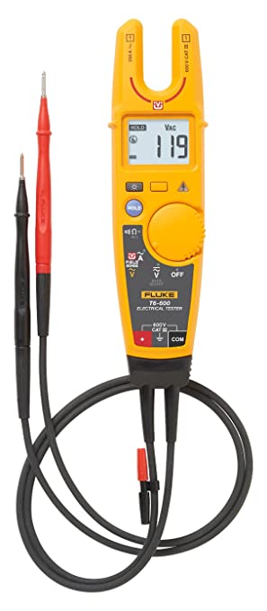
A Volt Meter is needed to read wires and the voltage of the system in various configurations.


You will also need a charged 12-volt battery. I just used our coach battery by running a red and black wire to the area I was working in. I plan to buy a 12-volt tool battery and a charger to make it easier to troubleshoot 12-volt systems on our rig.
Troubleshooting
The following Step Test Procedures are provided to troubleshoot and test all of the Kwikee Automatic Electric Step functions. They are designed to initially check the step’s basic functions separately from the RV wiring to determine whether or not the step is malfunctioning. The following procedures test the various components of the step until the source of the malfunction is located. Using these procedures will shorten and reduce the time spent troubleshooting.
Step Test Procedures
- Inspect the step for visible damage that might restrict the step’s operation.
- Obtain a 4-way pigtail connector Part Number 369243.
- Disconnect the 4-way connector on the underside of the step and connect the step-half of the connector with the 4-way connector pigtail.
- Set a fully charged 12-volt DC battery beside the step. Note: Do not allow the battery terminals to come in contact with the step. Complete a ground-for-step testing by connecting a 10 AWG wire from the negative battery terminal to the green ground wire of the control unit.
- For the power supply, attach the red wire from the pigtail to the positive battery terminal.
- With the power and ground connections complete, all functions of the control unit can be checked at the four wires of the pigtail. The brown wire is the door switch, the white wire is the power switch, and the yellow wire is the ignition override.
- To extend the step, touch the white wire to the positive battery terminal. The step should extend and remain extended. Our steps did not work here. This told me that either the control unit or the motor was bad. When I tested the motor, it also failed, letting me know the motor was bad. If your steps extend, continue on.
- To retract the step, hold the white wire to the positive battery terminal and touch the brown wire to the negative battery terminal.
- To test the Ignition Override feature, extend the step. With the step extended, disconnect the white wire from the battery and attach the brown wire to the battery’s negative terminal. Next, touch the yellow wire to the positive battery terminal. The step should retract. Remove the brown wire, and the step should extend.
- To test the “Last Out” feature, touch the brown wire to the negative battery terminal to retract the step. While holding the brown wire to the negative battery terminal, remove the yellow wire from the positive battery terminal. The step will stay retracted. Now, remove the brown wire. The step should extend.
- If any of the step functions do not work, the source of the malfunction is either in the control unit and/or the motor. Proceed to the “Testing the Motor” section.
If all of the step functions do work, the malfunction is either in the door switch, power switch, or vehicle wiring. Proceed to the “Testing the 4-way Connector” section.
Testing the Motor
WARNING: Do not leave the wires connected during this test once the step has cycled either in or out. Failure to remove the wires from the battery will burn out the motor voiding any warranty.
Disconnect The 2-Way Connector Between The Step Motor And The Control Unit. Install the 2-way connector/pigtail Part Number 369413.
- Connect the red motor wire to the positive battery terminal and touch the yellow motor wire to the negative battery terminal to extend the step. To retract the step, reverse the connections. If the step extends and retracts during this test, the condition of the step motor is good. To retract the step, reverse the connections. If the step extends and retracts during this test, the condition of the step motor is good.
- If you hear a grinding noise when the steps reach their fully retracted or fully extended position, it indicates that the plastic gear inside the motor is stripped and needs to be replaced. I had trouble finding the right gear for our step motor, so it may be easier to just replace the motor.
Note: On steps with reverse polarity plug Part Number 365884, reverse the red and yellow wire connections to perform the previous test.
Testing The 4-Way Connector
WARNING: Do not leave the wires connected during this test once the step has cycled either in or out. Failure to remove the wires from the battery will burn out the motor, voiding any warranty.
- To check the main power source, connect a voltmeter between the red wire from the 4-way connector (vehicle half) and the ground terminal at the end of the control unit’s green ground wire. The reading should be a minimum of 12 volts DC.
- If the voltage reading is low, there may be a loose or corroded connection at the battery, a low charge level on the battery itself, or a poor ground. If the voltage reading is 0 volts, check the step fuse/circuit breaker, all connections, and the condition of the wiring between the battery and the plug, including the ground connection at the chassis.
- To check the override switch, connect a voltmeter between the white wire from the 4-way connector (vehicle half) and the terminal at the end of the control unit’s green ground wire. The reading should be a minimum of 12 volts DC when the switch is on, and 0 volts DC when the switch is off.
- If the voltmeter reads 0 volts when the override switch is on, there is a problem with the override switch circuit. Check the 6 amp in-line fuse, the override switch itself, and the condition of the circuit wiring and terminal connections.
- To check the door switch, connect a voltmeter between the red wire from the 4-way connector (vehicle half) and the brown wire in the same connector. The voltage should be a minimum of 12 volts DC when the door is closed and 0 volts DC when the door is open
- If the readings are incorrect, there is a problem with the switch. Check the door switch and the condition of the circuit’s wiring and terminal connections.
- To check the ignition override system, connect a voltmeter between the yellow wire from the 4-way connector (vehicle half) and the ground terminal on the end of the control unit’s green ground wire. The voltage reading should be approximately 12 volts DC when the ignition is on and 0 volts when the ignition is off.
- If the reading is zero when the ignition is on, check all terminal connections, wiring, and the vehicle ignition fuse.
- For steps equipped with door switch only operation: Connect the white jumper wire from the vehicle half of the 4-way connector and the ground terminal at the end of the control unit’s green ground wire.
- Note: Be sure to use the terminal with only the white wire. The reading should be 0 volts DC. If the voltage reading is higher, the white wire is connected to 12 volts DC and should be cut.
If you have additional questions or need more assistance, contact Lippert Components, Inc. Customer Service at 1-574-537-8900.
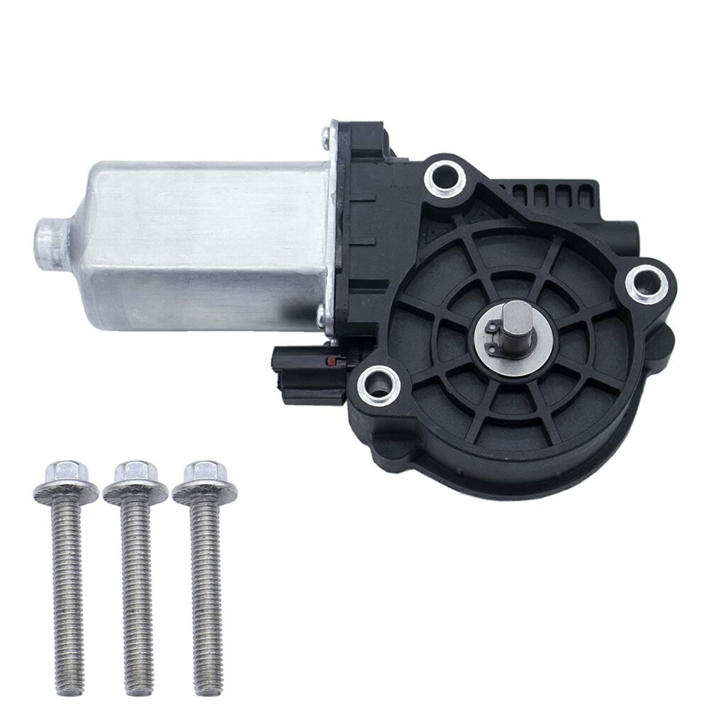
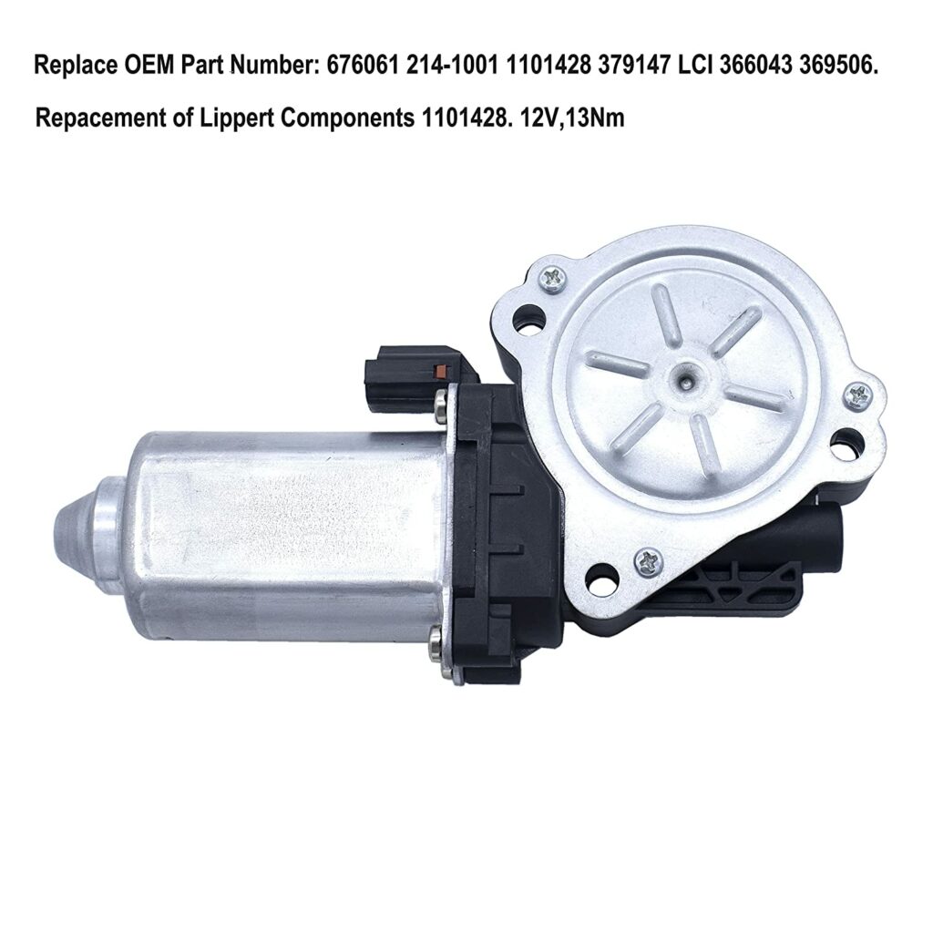
Replacing the Step Motor
Once I figured out that the motor was the problem, I looked for a replacement. Camping World wanted between $117 and $135 for a replacement motor. So I decided to look on Amazon. The Lippert Motor Part Number for our steps is 676061. I found a few different replacement motors on Amazon for under $50.
Motor Replacement Procedures
- Disconnect power to the step.
- Disconnect the power plug from the motor assembly.
- To gain access to the motor, since our steps were retracted, I had to drop down the whole gearbox/motor assembly. To do this, loosen the four nuts and lock washers of the gear assembly to lower it down. This will give access to the linkage arm cotter pin. Remove the cotter pin and pin on the linkage. The steps should move freely.
- Remove the 3 screws holding the motor assembly.
- Lower it straight down, being certain not to drop the gear, washers, and pin on the gear assembly side of the motor.
- Move the washers, gear, and pin to the new motor.
- Apply new grease to the gear if needed.
- Insert the motor assembly into the gearbox and insert the three screws.
- Tighten the screws down.
- Reinstall the gearbox linkage arm on the step mechanism with the pin and cotter pin removed earlier.
- Reinstall the gearbox and motor assembly using the four nuts and washers removed earlier.
- Reconnect the two-way power plug to the motor assembly.
- Reconnect the main step power (four-way connector) while staying clear of moving parts. Warning: As soon as power is applied steps will move to the correct position. We recommend having the door open so the steps move to the extended position.
- Test Step operation.
Once the motor arrived, it only took me about 15 minutes to install it and get the steps back in working order.
Gearbox Replacement Procedures
If you found that the Gearbox was the problem with your steps, below you’ll find the steps to replace it.

- Disconnect power from the step.
- Disconnect the power plug from the motor assembly.
- Loosen the four nuts and lock washers on each corner of the gear assembly to lower the assembly. This will give access to the linkage arm cotter pin.
- Remove the cotter pin and pin from the arm connecting the step to the gear assembly.
- Finish removing the four nuts and lock washers on each corner of the gear assembly.
- Remove the 3 screws holding the motor assembly
- Lower it straight down, being certain not to drop the gear, washers, and pin on the gear assembly side of the motor
- Remove the gear assembly and replace it with a new one (it should already be pre-greased).
- Reinstall the motor using the new inner gear (the small one) from the gear assembly.
- Insert the three bolts securing the motor.
- Reinstall the gearbox linkage arm on the step mechanism with the pin and cotter pin removed earlier.
- Reinstall the gearbox and motor assembly using the four nuts and washers removed earlier.
- Reconnect the main step power (four-way connector) while staying clear of moving parts.
- Test Step operation.
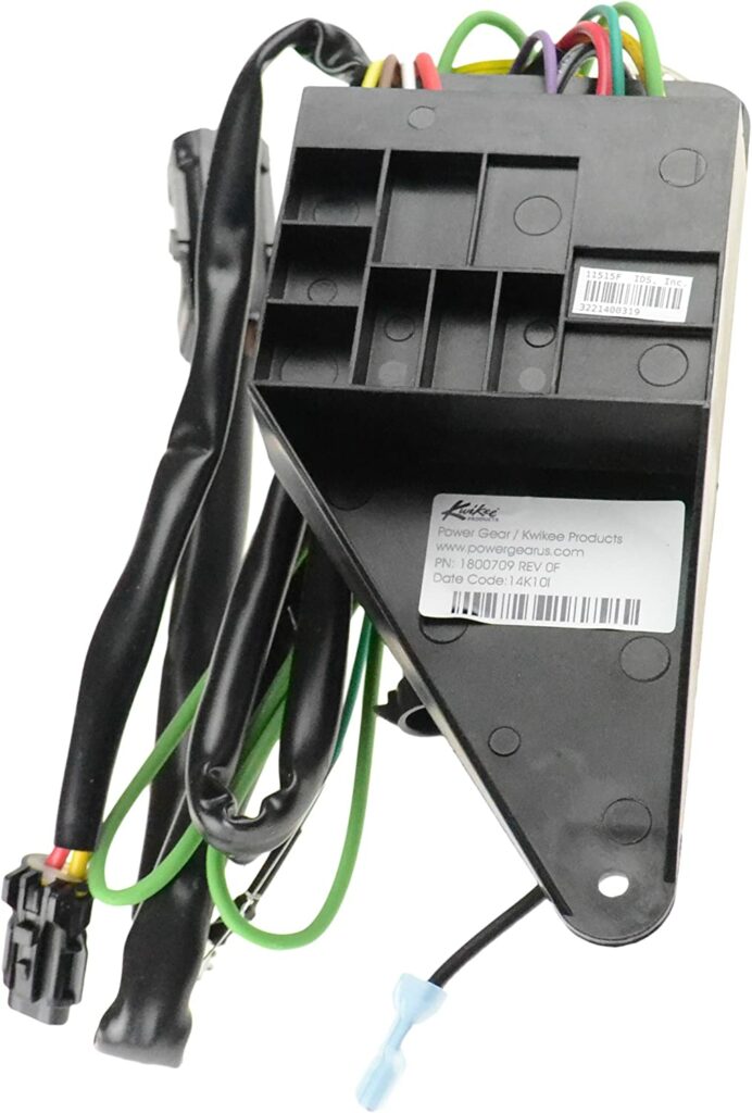
Replacing Control Board
If you found that the Control Board is the failed part, below are steps to change it out.
- Disconnect the main connector to the step and controller unit.
- Remove the bolts securing the controller board (leave wires connected).
- Replace the controller board with the new one and secure it with the bolts.
- Move each wire from the old controller to the new controller.
- Reconnect the main plug to the step.
- Verify proper step operation.
Conclusion
If you have electric steps then eventually the motor, gearbox, or one of these other components will probably wear out and need replacing. I hope I gave you enough information here to inspire you to repair it yourself. It really isn’t a hard process.
Have you had problems with your Kwikee/Lippert Electric Steps? Was it easy to fix it yourself?
Thank you for taking the time to read our article please let us know if you have any questions or comments below.
If you’re looking to build your own home-based business like we have with this webpage, check out Wealthy Affiliate.
Wealthy Affiliate is an all-in-one platform that you can build your whole affiliate marketing business on. It combines training, software, and website hosting into one. This makes the whole process of starting an online business from scratch much easier, especially if you’re new to building a website.

New Stept, connected the red to positive terminal and green to ground of the battery and the Stept wanted to retract when already in retract position every time touch green wire to ground would only retract mode any comments?
What step of the troubleshooting are you on when you are having this issue? You’re going to want to follow the troubleshooting instructions in the post exactly. Don’t skip any steps.
When I test the yellow wire at the 4 way connector I have 12volt when the switch is off and 0 volts when the switch is on
Hi Mike, The Yellow wire is the ignition override wire. Are you talking about the ignition switch? From my understanding the yellow wire should be hot with the ignition on. I don’t know why you would be getting the opposite. The yellow wire works in conjunction with the door switch (Brown wire) to move the steps if the ignition is on. It could be something up with that. Let me know what you find out with it. Good Luck.